
TM 5-3805-292-23
0024
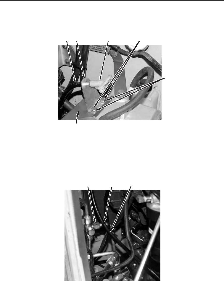
REMOVAL CONTINUED
3. Remove dipstick (Figure 2, Item 3) from dipstick tube (Figure 2, Item 1).
4. Remove two bolts (Figure 2, Item 4), and washers (Figure 2, Item 5), and dipstick tube bracket (Figure 2, Item
2) from cooling fan housing (Figure 2, Item 6).
3
1
4
2
5
458-1075
6
Figure 2. Dipstick Tube Bracket.
0024
N OT E
Cut and discard tiedown straps on removal. Install new tiedown straps on installation.
5. Remove tiedown strap (Figure 3, Item 2) from line (Figure 3, Item 1) and engine oil dipstick tube (Figure 3,
Item 3).
3
1
2
4
458-1075
Figure 3. Dipstick Tube Tiedown Strap.
0024