
TM 5-3805-292-23
0024
INSTALLATION
00024
1. Position oil dipstick tube and bracket assembly on machine.
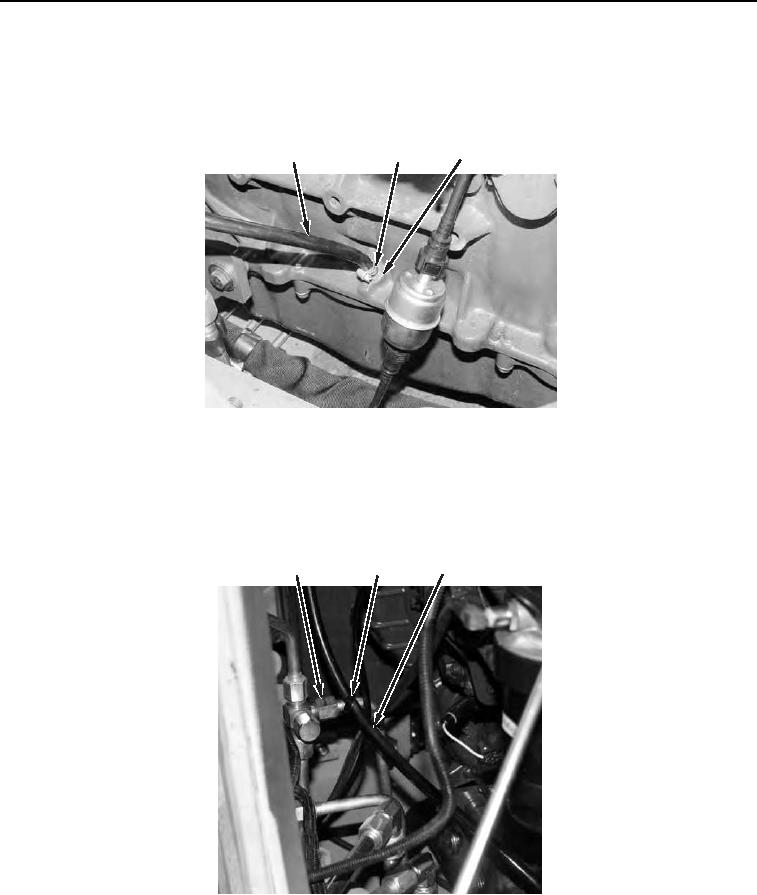
2. Install oil dipstick tube (Figure 5, Item 1) and clamp (Figure 5, Item 2) to engine block (Figure 5, Item 3).
Tighten clamp.
3
1
2
458-1075
Figure 5. Dipstick Tube and Clamp.
0024
3. Install new tiedown strap (Figure 6, Item 2) to line (Figure 6, Item 1) and engine oil dipstick tube (Figure 6,
Item 3).
3
1
2
4
458-1075
Figure 6. Dipstick Tube Tiedown Strap.
0024