
TM 5-3805-292-23
0030
REMOVAL CONTINUED
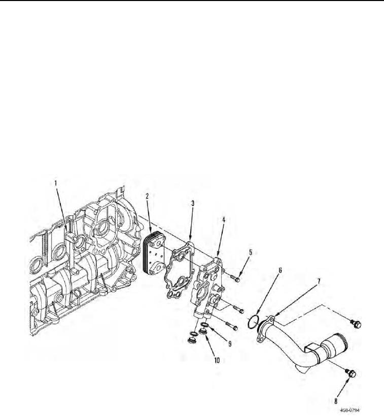
4. Remove three bolts (Figure 3, Item 8), pipe (Figure 3, Item 7), and O-ring (Figure 3, Item 6) from machine.
Discard O-ring.
N OT E
Use a container to catch any fluid that may drain from hoses or system. Dispose of fluid
IAW local policy and ordinances. Ensure all spills are cleaned up.
N OT E
Note location and length of bolts to aid in installation.
5. Remove 12 bolts (Figure 3, Item 5), housing (Figure 3, Item 4), gasket (Figure 3, Item 3), and cooler (Figure 3,
Item 2) from engine (Figure 3, Item 1). Discard gasket.
6. Remove two plugs (Figure 3, Item 10) and gaskets (Figure 3, Item 9) from housing (Figure 3, Item 4). Discard
gaskets.
Figure 3. Engine Oil Cooler.
0030