
TM 5-3805-292-23
0055
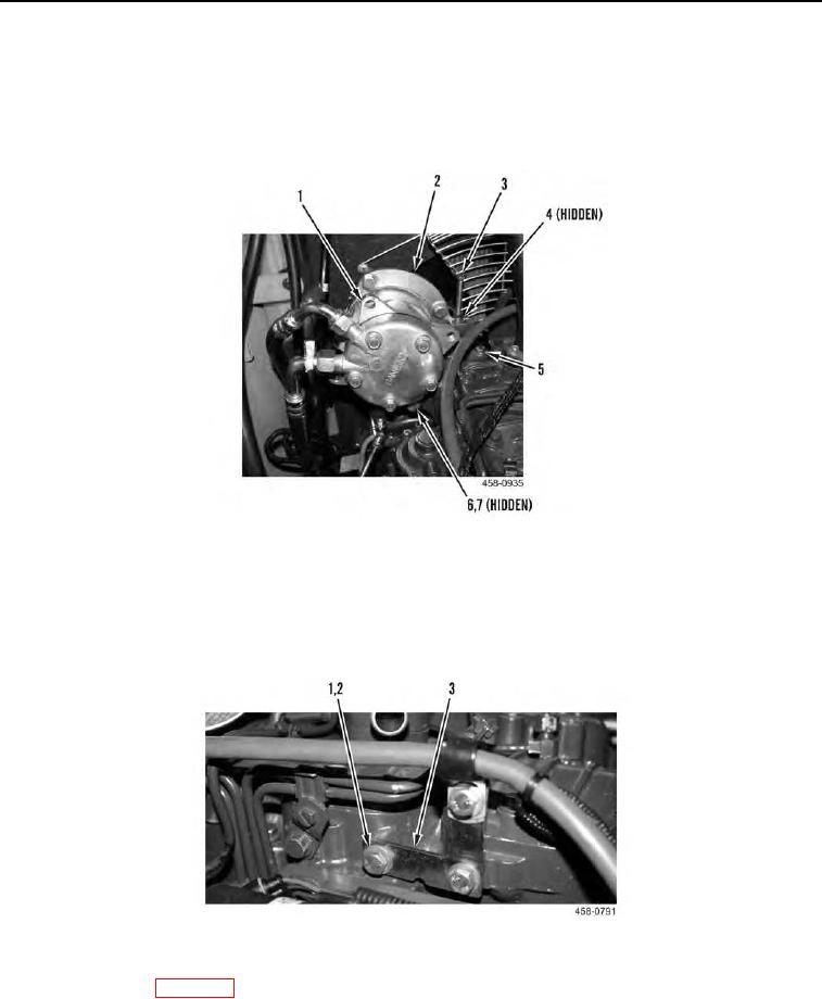
INSTALLATION CONTINUED
3. Position assembled A/C compressor and mounting bracket (Figure 7, Item 1) on machine and install three
bolts (Figure 7, Item 5).
4. Install serpentine belt (Figure 7, Item 2) on assembled A/C compressor and mounting bracket (Figure 7, Item
1) and tighten bolts (Figure 7, Items 3, 4, 6, and 7)
Figure 7. Assembled A/C Compressor and Mounting Bracket.
0055
5. Return throttle to idle position (TM 5-3805-292-10).
6. Position bracket (Figure 8, Item 3) and install two washers (Figure 8, Item 2) and bolts (Figure 8, Item 1) on
right side of engine.
Figure 8. Air Duct Heater Bracket.
0055
7. Adjust valve lash (WP 0056).
END OF TASK