• Home
  • Download PDF
  • Order CD-ROM
  • Order in Print
Figure 2. Assembled A/C Compressor and Mounting Bracket.
Figure 4. Housing Disassembly.

Field Maintenance Manual For M400T And M400W
Page Navigation
  405    406    407    408    409  410  411    412    413    414    415  
img
.
TM 5-3805-292-23
0055
REMOVAL CONTINUED
N OT E
Note size and location of bolts prior to removal.
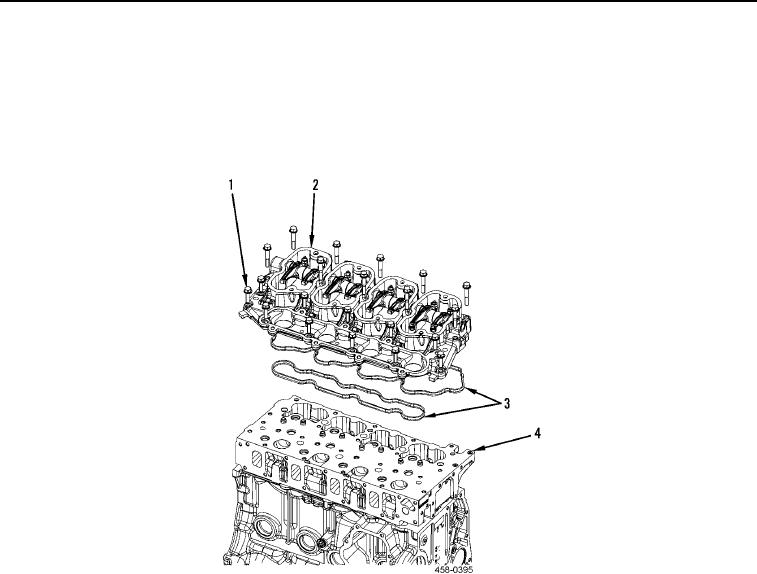
5. Remove 21 bolts (Figure 3, Item 1), housing (Figure 3, Item 2), and two gaskets (Figure 3, Item 3) from cylin-
der head (Figure 3, Item 4). Discard gaskets.
Figure 3. Housing Removal.
0055
END OF TASK
0055-3


Privacy Statement
Press Release
Contact

© Copyright Integrated Publishing, Inc.. All Rights Reserved.