
TM 5-3805-292-23
0066
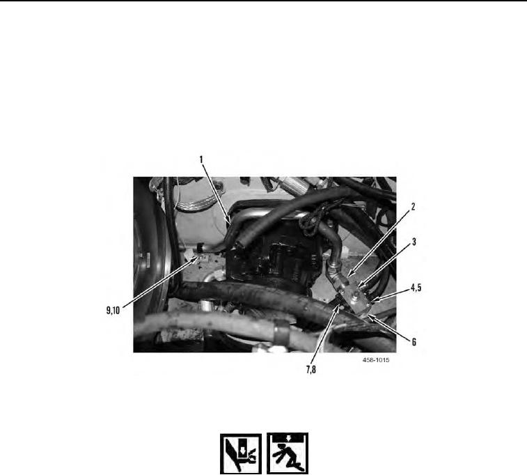
REMOVAL CONTINUED
2. Disconnect and remove hydraulic hose (Figure 2, Item 7) and clamp (Figure 2, Item 8) from return oil manifold
(Figure 2, Item 3).
3. Remove bolt (Figure 2, Item 9) and clamp (Figure 2, Item 10) from tube (Figure 2, Item 1).
4. Loosen fitting (Figure 2, Item 2) and disconnect tube (Figure 2, Item 1) from return oil manifold (Figure 2, Item
3).
5. Remove two bolts (Figure 2, Item 4), washers (Figure 2, Item 5), and spacers (Figure 2, Item 6) from return oil
manifold (Figure 2, Item 3) and position manifold aside.
Figure 2. Return Oil Manifold.
0066
WARN I N G
Use assistance when lifting heavy parts. Failure to follow this warning may result in injury
to personnel.
N OT E
Note orientation of hydraulic drive motor before removal. Hydraulic drive motor weighs
130 lb (59 kg).
6. With assistance, attach lifting device and remove six nuts (Figure 3, Item 8), bolts (Figure 3, Item 4), washers
(Figure 3, Item 3), and hydraulic drive motor (Figure 3, Item 1) from machine.
7. Set hydraulic drive motor (Figure 3, Item 1) on flat surface and remove lifting device.
8. Remove hose (Figure 3, Item 7) and clamp (Figure 3, Item 2) from hydraulic drive motor (Figure 3, Item 1).
9. Disconnect and remove three hydraulic lines (Figure 3, Item 5) and fittings (Figure 3, Item 6) from hydraulic
drive motor (Figure 3, Item 1).