
TM 5-3805-292-23
0068
INSTALLATION CONTINUED
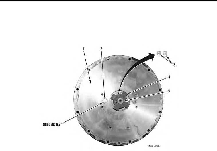
3. Tighten two setscrews (Figure 6, Item 3) to 37 to 40 lb-ft (50 to 54 Nm) on coupling (Figure 6, Item 4).
4. Install plate (Figure 6, Item 1), two nuts (Figure 6, Item 7), four washers (Figure 6, Item 6), and two bolts (Fig-
ure 6, Item 2) on tandem pump (Figure 6, Item 5).
5. Tighten two bolts (Figure 6, Item 2) to 35 to 45 lb-ft (47 to 61 Nm).
Figure 6. Plate and Coupling.
0068