TM 5-3805-292-23
0093
CHARGING CONTINUED
N OT E
Keep high-side valve closed on manifold gauge set while charging the A/C system.
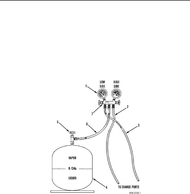
8. Slowly open low-side valve (Figure 3, Item 1) on manifold gauge set (Figure 3, Item 7).
9. Continue charging until bubbles disappear from receiver/dryer sight glass and high-side/low-side pressures
are within acceptable range.
10. Close refrigerant tank valve (Figure 3, Item 5) on R-134a refrigerant tank (Figure 3, Item 4).
11. Close low-side valve (Figure 3, Item 1) on manifold gauge set (Figure 3, Item 7).
12. Shut off engine (TM 5-3805-292-10).
13. Disconnect charging hose (Figure 3, Item 6) from R-134a refrigerant tank valve (Figure 3, Item 5).
14. Disconnect manifold gauge set (Figure 3, Item 7) from A/C compressor.
15. Operate A/C system to verify correct operation (TM 5-3805-292-10).
Figure 3. Charging Hook-Up.
0093
END OF TASK
FOLLOW-ON TASKS
00093
Verify correct operation of machine (TM 5-3805-292-10).
END OF TASK
END OF WORK PACKAGE
0093-7/(8 blank)

