• Home
  • Download PDF
  • Order CD-ROM
  • Order in Print
Figure 5. LH Joystick Console Bracket.
Figure 7. Bracket Plate.

Field Maintenance Manual For M400T And M400W
Page Navigation
  695    696    697    698    699  700  701    702    703    704    705  
img
.
TM 5-3805-292-23
0102
INSTALLATION CONTINUED
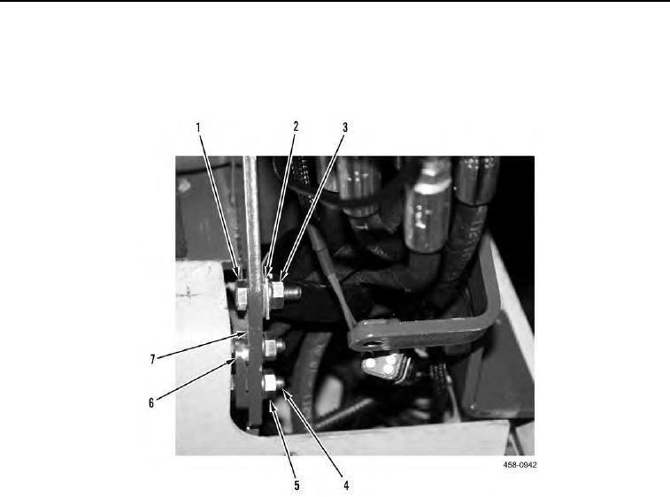
4. Install bolt (Figure 6, Item 1), clamp (Figure 6, Item 2), and nut (Figure 6, Item 3) on machine.
5. Position hose bracket (Figure 6, Item 6) on joystick console bracket (Figure 6, Item 7) and install two bolts (Fig-
ure 6, Item 4), and nuts (Figure 6, Item 5) on machine.
Figure 6. Clamp and Hose Bracket.
0102
0102-6


Privacy Statement
Press Release
Contact

© Copyright Integrated Publishing, Inc.. All Rights Reserved.