
8
TM 5-3805-292-23
FIELD MAINTENANCE
-
LH JOYSTICK CONSOLE BRACKET REPLACEMENT
0
102
REMOVAL, CLEANING AND INSPECTION, INSTALLATION
INITIAL SETUP
References
Tools and Special Tools
0
0
Tool Kit, General Mechanic's (WP 0178, Item
TM 5-3805-292-23P, Figure 52
0
33)
0
Equipment Conditions
0
Materials/Parts
LH Joystick valve removed (WP 0084)
0
0
Cleaning Compound, Solvent, Type III (WP
Charging system protection resistor removed
0179, Item 3)
0
0
Rag, Wiping (WP 0179, Item 19)
Machine parked on level ground (TM 5-3805-
0
292-10)
0
References
0
Estimated Time to Complete
TM 5-3805-292-10
0
0
3.0 Hr
0
0
0
REMOVAL
000102
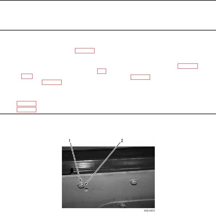
1. Remove two bolts (Figure 1, Item 2) and washers (Figure 1, Item 1) from machine.
Figure 1. Bracket Mounting Bolts.
0102