
TM 5-3805-292-23
0105
INSTALLATION CONTINUED
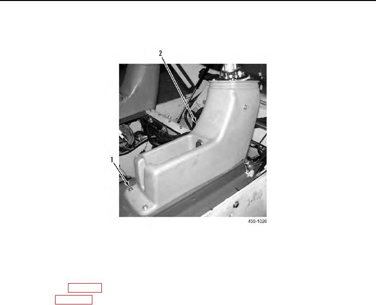
3. Install console (Figure 4, Item 2) and four bolts (Figure 4, Item 1) on machine.
Figure 4. Joystick Console Replacement.
0105
END OF TASK
FOLLOW-ON TASKS
000105
1. Install dust boot (WP 0101).
2. Close ROPS (WP 0134).
3. Verify correct operation of machine (TM 5-3805-292-10).
END OF TASK
END OF WORK PACKAGE
0105-5/(6 blank)