
TM 5-3805-292-23
0108
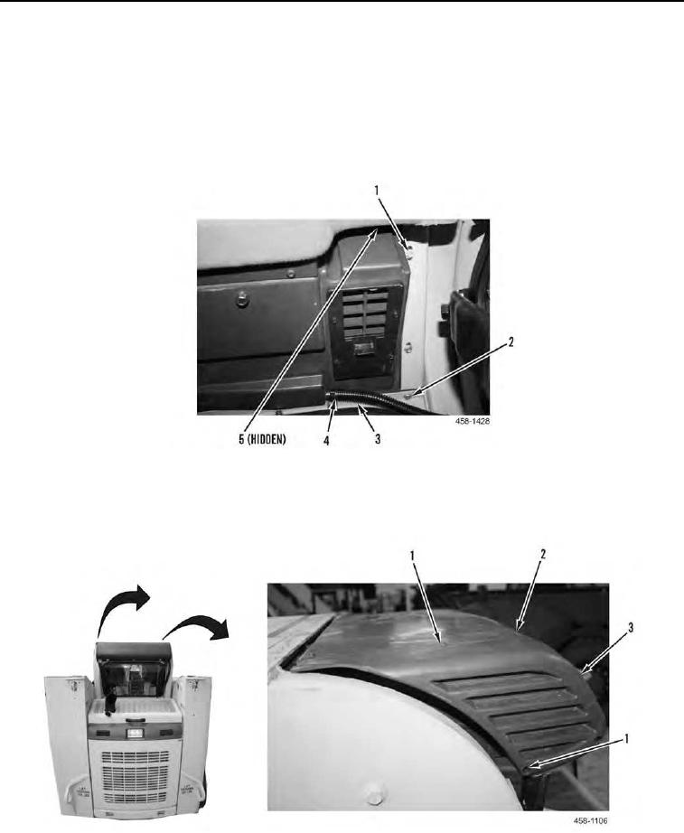
INSTALLATION CONTINUED
6. Install two screws (Figure 13, Item 2) and four bolts (Figure 13, Items 1 and 5) on machine.
N OT E
Remove all caps from ports and hoses and install hoses as noted during removal.
7. Connect two drain hoses (Figure 13, Item 3) and install two clamps (Figure 13, Item 4) on each side of HVAC
case.
Figure 13. Case, Drain Hoses, and Retaining Hardware.
0108
8. Install two end cap covers (Figure 14, Item 3) and eight screws (Figure 14, Item 1) on case (Figure 14, Item 2).
Figure 14. End Cap Covers and Retaining Hardware.
0108