
TM 5-3805-292-23
0108
REMOVAL CONTINUED
N OT E
Tag and mark all hoses to aid installation.
Cap all ports and open holes immediately upondisconnection to prevent dirt from entering
system.
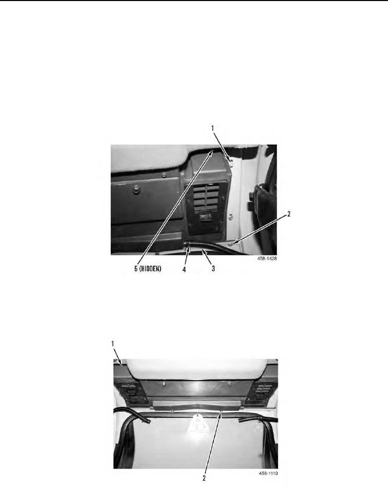
4. From inside cab, release two clamps (Figure 4, Item 4) and disconnect two drain hoses (Figure 4, Item 3) from
each side of HVAC case.
5. Remove four bolts (Figure 4, Items 1 and 5) and two screws (Figure 4, Item 2) from machine.
Figure 4. Case, Drain Hoses, and Retaining Hardware.
0108
6. Remove two nuts (Figure 5, Item 2) from machine.
7. With assistance, slide deluxe heater A/C assembly (Figure 5, Item 1) rearward and position aside.
Figure 5. Deluxe Heater A/C Assembly Removal.
0108