
TM 5-3805-292-23
0109
REMOVAL CONTINUED
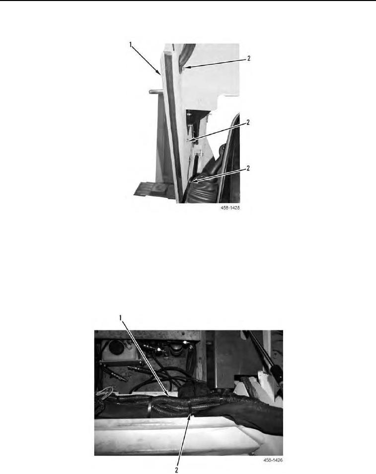
9. Remove three bolts (Figure 5, Item 2) and outer cover (Figure 5, Item 1) from machine.
Figure 5. Outer Cover.
0109
10. Inside cab, remove tiedown straps (Figure 6, Item 2). Position wiring harness and heater hoses (Figure 6, Item
1) aside. Discard tiedown straps.
C AU T I O N
Do NOT cut wiring harness. Failure to follow this warning may result in damage to the
equipment.
11. Cut A/C hoses and remove from machine.
Figure 6. Wiring Harness and Heater Hose.
0109