
TM 5-3805-292-23
0109
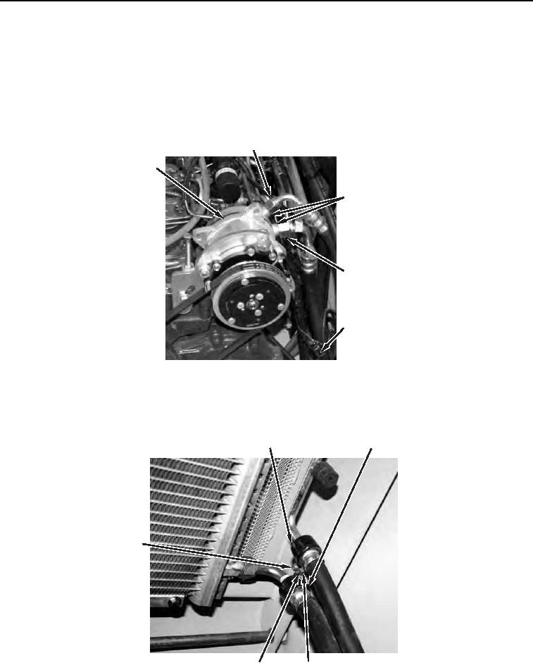
REMOVAL CONTINUED
N OT E
Tag and cap all hoses and fittings.
Note routing of hoses to aid in installation.
12. Disconnect hoses (Figure 7, Item 2 and 4) from A/C compressor (Figure 7, Item 1). Remove and discard two
O-rings (Figure 7, Item 3). Remove and discard tiedown straps (Figure 7, Item 5).
13. Remove hose (Figure 7, Item 4) from machine.
2
1
1
3 (HIDDEN)
4
5
458-0820
Figure 7. A/C Compressor.
0109
14. Open engine compartment hood and remove nut (Figure 8, Item 4), washer (Figure 8, Item 3), outer clamp
(Figure 8, Item 1) and inner clamp (Figure 8, Item 2) from bolt (Figure 8, Item 5).
1
2
5
458-1055
3
4
Figure 8. Clamp.
0109