
TM 5-3805-292-23
0109
INSTALLATION CONTINUED
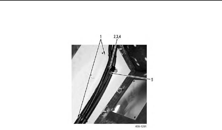
12. Install clamp (Figure 15, Item 5), bolt (Figure 15, Item 2), washer (Figure 15, Item 3), and nut (Figure 15, Item
4) to machine. Install new tiedown straps (Figure 15, Item 1) to machine.
Figure 15. Hoses.
0109
N OT E
Route hoses as noted during removal.
Install hoses as tagged during removal.
13. Install hose (Figure 16, Item 5) on machine.
14. Install new O-ring (Figure 16, Item 2) and connect hose (Figure 16, Item 5) to hose (Figure 16, Item 6).
15. Install new O-ring (Figure 16, Item 2) and connect hose (Figure 16, Item 1) to receiver/dryer (Figure 16,
Item 3).
16. Install hose (Figure 16, Item 4) on machine.