
TM 5-3805-292-23
0113
REMOVAL CONTINUED
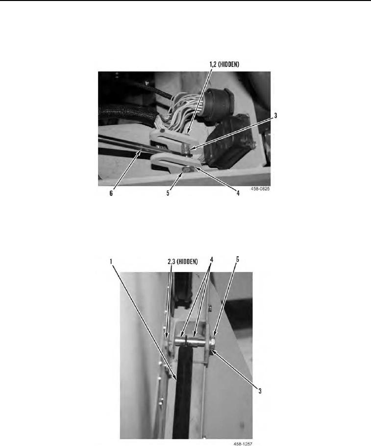
7. Remove nut (Figure 5, Item 5) and washer (Figure 5, Item 4) from through bolt (Figure 5, Item 1).
8. Remove through bolt (Figure 5, Item 1), two spacers (Figure 5, Item 3), and washer (Figure 5, Item 2) from
lower end of pivot strut (Figure 5, Item 6).
Figure 5. LH ROPS Auxiliary Pivot Strut Through Bolt (Lower End).
0113
9. Remove through bolt (Figure 6, Item 5), two washers (Figure 6, Item 3), spacers (Figure 6, Item 4) and nut
(Figure 6, Item 2) from upper end of LH ROPS auxiliary pivot strut (Figure 6, Item 1).
10. Remove LH ROPS auxiliary pivot strut (Figure 6, Item 1) from machine.
Figure 6. LH ROPS Auxiliary Pivot Strut (Upper End).
0113
END OF TASK