
TM 5-3805-292-23
0154
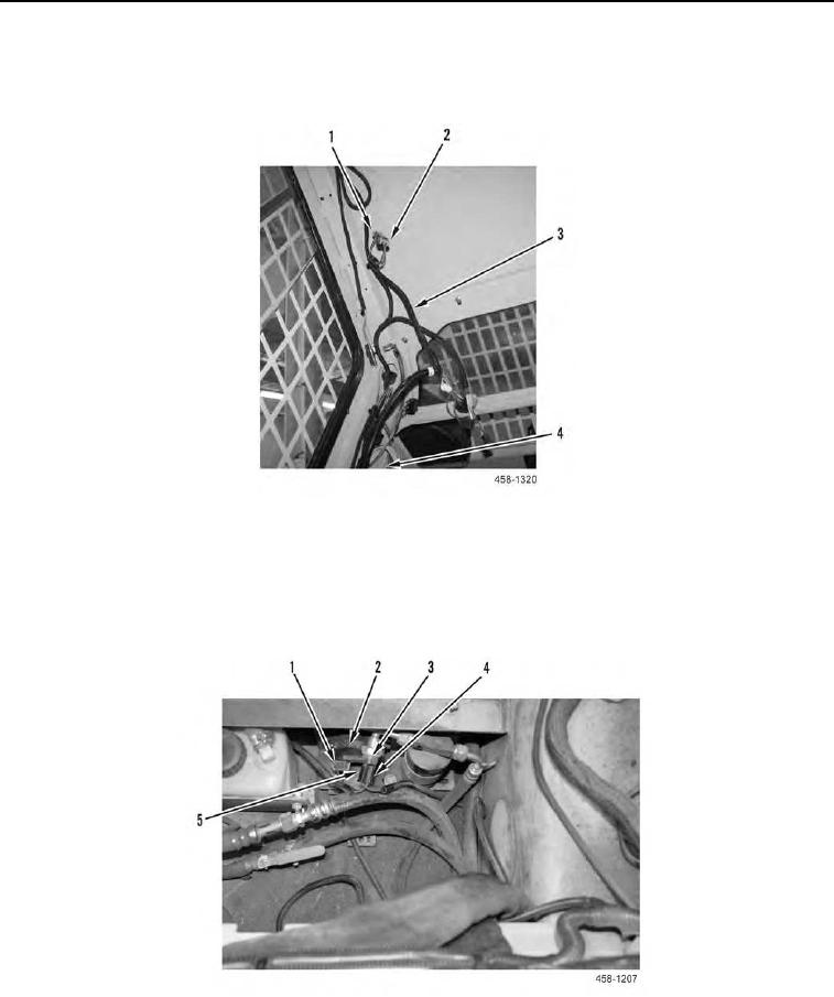
HVAC WIRING HARNESS REMOVAL CONTINUED
10. Disconnect electrical connector (Figure 8, Item 1) from connector (Figure 8, Item 2) and remove HVAC wiring
harness (Figure 8, Item 3) from LH channel of ROPS (Figure 8, Item 4).
Figure 8. HVAC Wiring Harness.
0154
11. Disconnect electrical connector (Figure 9, Item 1) from heater control valve (Figure 9, Item 2).
12. Disconnect electrical connector (Figure 9, Item 4) from pressure switch (Figure 9, Item 3).
13. Remove HVAC wiring harness from machine.
Figure 9. HVAC Wiring Harness and A/C Clutch Harness Leads.
0154
END OF TASK