
TM 5-3805-292-23
0154
CLEANING AND INSPECTION
000154
Clean and inspect all parts IAW Mechanical General Maintenance Instructions (WP 0172).
END OF TASK
HVAC WIRING HARNESS INSTALLATION
000154
N OT E
Route HVAC wiring harness as noted during removal.
Connect electrical connections as tagged during removal.
Secure A/C clutch wiring harness with tiedown straps.
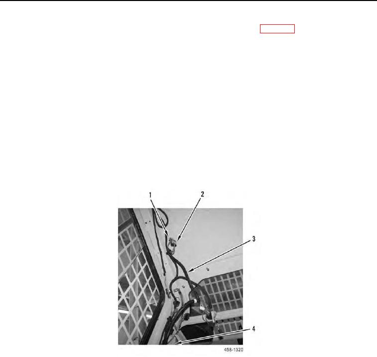
1. Connect electrical connector (Figure 10, Item 4) to pressure switch (Figure 10, Item 3).
2. Connect electrical connector (Figure 10, Item 1) to heater control valve (Figure 10, Item 2).
3. Pull HVAC wiring harness (Figure 10, Item 3) through LH channel of ROPS (Figure 10, Item 4) and connect
electrical connector (Figure 10, Item 1) to connector (Figure 10, Item 2).
Figure 10. HVAC Wiring Harness.
0154