TM 5-3805-298-23-1
0002
LOCATION AND DESCRIPTION OF MAJOR COMPONENTS
0002
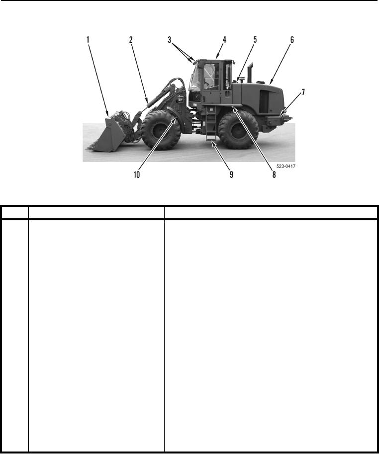
Figure 1. 924H Loader Left Side 1 of 3.
0002
KEY
COMPONENT
DESCRIPTION
MP Bucket
Hardened-steel, multi-purpose bucket has cutting edges,
1
teeth, and wear plates that can be replaced by Field Mainte-
nance. Hydraulic cylinder-activated clamshell jaws open and
close to pick up debris (rocks, tree limb, etc.).
2
Tilt Cylinder
Single hydraulic cylinder tilts work tool.
3
Front Worklights
Illuminate work area to front of machine. Mounted to roof
bracket on both sides of machine.
4
ROPS/FOPS
Bolt-on structure provides rollover and falling object protection
for operator. Must be removed for transport by C-130 aircraft,
highway, and GIC rail.
5
Hydraulic Tank
Stores hydraulic fluid used in machine hydraulic systems.
Contains sight gage for fluid level check.
6
Engine Enclosure Access Door
Gull-wing design with gas strut lifts for access to filters and
service points. Located on both sides of machine.
7
Battery Box
Provides protection for batteries. There is one battery in each
box, located on both sides of machine.
8
Platforms
Skid-free surface for gaining access to top of machine.
Located on both sides of machine.
9
Ladders
Provide access to cab and platform. Located on both sides of
machine.
10
Fenders
Located over front tire, on both sides of machine.

