
TM 5-3805-298-23-2
0177
REMOVAL CONTINUED
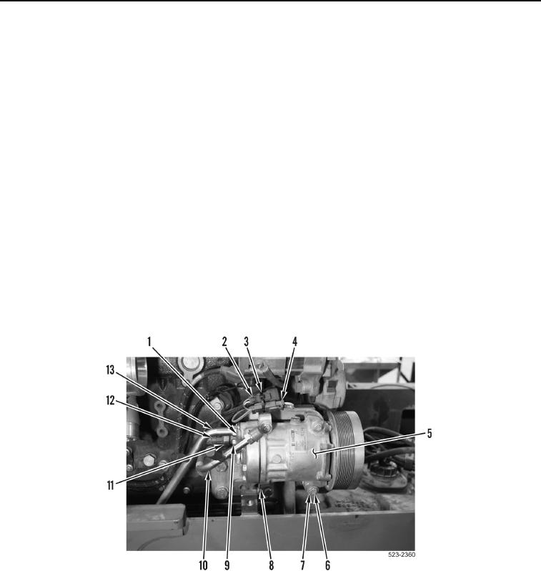
77. Remove tiedown strap (Figure 45, Item 3) from engine wiring harness connector (Figure 45, Item 2). Discard
tiedown strap.
78. Disconnect A/C compressor clutch connector (Figure 45, Item 4) from engine wiring harness connector
(Figure 45, Item 2).
CAUTION
Cap all openings along with component connections during removal to protect against
contamination. Failure to follow this caution may result in damage to equipment.
NOTE
Tag and mark all hoses and tubes to aid in installation.
Note routing of hoses and tubes for installation.
79. Remove bolt (Figure 45, Item 9), clamp (Figure 45, Item 1) and tubes (Figure 45, Item 10 and 13) from A/C
compressor (Figure 45, Item 5).
80. Disconnect engine wiring harness connector (Figure 45, Item 12) from A/C high pressure switch
(Figure 45, Item 11).
81. Remove four bolts (Figure 45, Item 6), washers (Figure 45, Item 7), ladder clip (Figure 45, Item 8) and A/C
compressor (Figure 45, Item 5) from machine.
Figure 45. A/C Compressor.
0177