
TM 5-3805-298-23-2
0177
INSTALLATION CONTINUED
CAUTION
Remove all caps from hydraulic openings and component connections during installation.
Failure to follow this caution may result in damage to equipment.
NOTE
Install hoses and tubes as noted during removal.
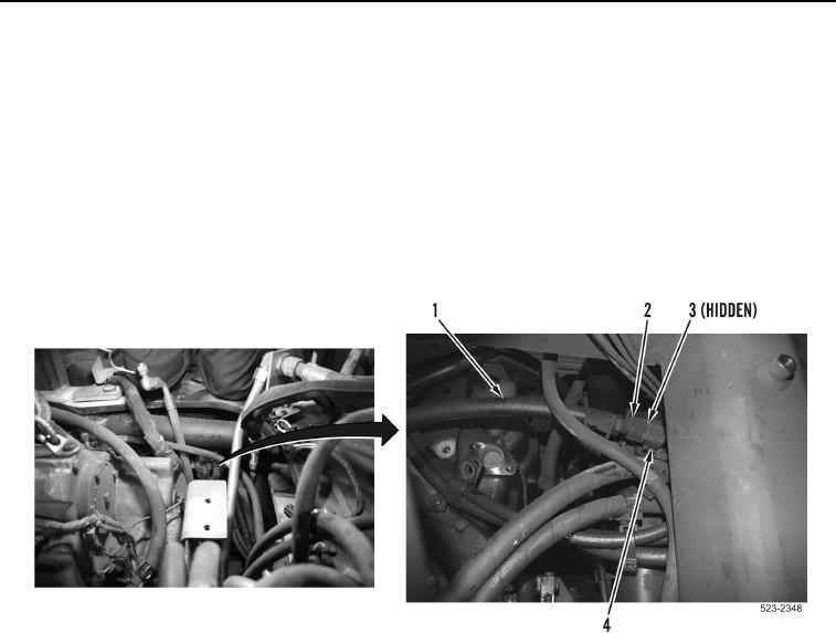
51. Install new O-ring (Figure 83, Item 3), hose (Figure 83, Item 1) and tighten tube nut (Figure 83, Item 2) on
transmission filter base (Figure 83, Item 4).
Figure 83. Transmission Filter Base.
0177