• Home
  • Download PDF
  • Order CD-ROM
  • Order in Print
Figure 86. Bracket and Tube Assembly.
Figure 88. Implement Control Valve.

Field Maintenance Manual For 924H Wheel Loader -2 Page Navigation
  582    583    584    585    586  587  588    589    590    591    592  
img
.
TM 5-3805-298-23-2
0177
INSTALLATION CONTINUED
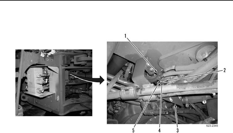
58. Install ladder clip (Figure 87, Item 2), two P-clamps (Figure 87, Item 1), washer (Figure 87, Item 5), and bolt
(Figure 87, Item 4) on bracket and tube assembly (Figure 87, Item 3).
Figure 87. Bracket and Tube Assembly.
0177
0177-76


Privacy Statement
Press Release
Contact

© Copyright Integrated Publishing, Inc.. All Rights Reserved.