
TM 5-3805-298-23-2
0178
ENGINE TRANSFER OF PARTS REMOVAL CONTINUED
NOTE
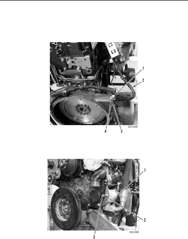
Note position and location of engine wiring harness for installation purposes.
18. Remove bolt (Figure 19, Item 3), washer (Figure 19, Item 4), bracket (Figure 19, Item 1) and engine wiring
harness (Figure 19, Item 2) from engine.
Figure 19. Engine Wiring Harness.
0178
19. Remove bolt (Figure 20, Item 3) and two washers (Figure 20, Item 2) from brake pump (Figure 20, Item 1).
Figure 20. Brake Pump.
0178