
TM 5-3805-298-23-2
0206
REMOVAL CONTINUED
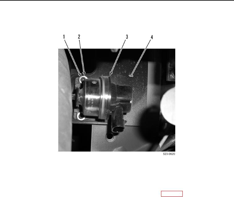
5. Remove two bolts (Figure 3, Item 1), washers (Figure 3, Item 2), and air inlet restriction switch (Figure 3,
Item 3) from air cleaner mounting bracket (Figure 3, Item 4).
Figure 3. Air Inlet Restriction Switch.
0206
END OF TASK
CLEANING AND INSPECTION
000206
Clean and inspect all parts IAW Mechanical General Maintenance Instructions (WP 0172).
END OF TASK
INSTALLATION
000206
1. Install air inlet restriction switch (Figure 3, Item 3), two washers (Figure 3, Item 2), and bolts (Figure 3, Item 1),
on air cleaner mounting bracket (Figure 3, Item 4).
2. Install air inlet restriction switch hose (Figure 2, Item 3) to air inlet restriction switch (Figure 2, Item 2).
3. Connect rear frame harness connector (Figure 2, Item 1) to air inlet restriction switch (Figure 2, Item 2).