
TM 5-3805-298-23-2
0207
TURBO OUTLET/AFTERCOOLER INLET HOSE INSTALLATION
000207
NOTE
One aftercooler hose is located at bottom of aftercooler. Other aftercooler hose is located
at top of aftercooler.
Remove plugs and caps from hoses and open ports.
Install hoses as noted during removal.
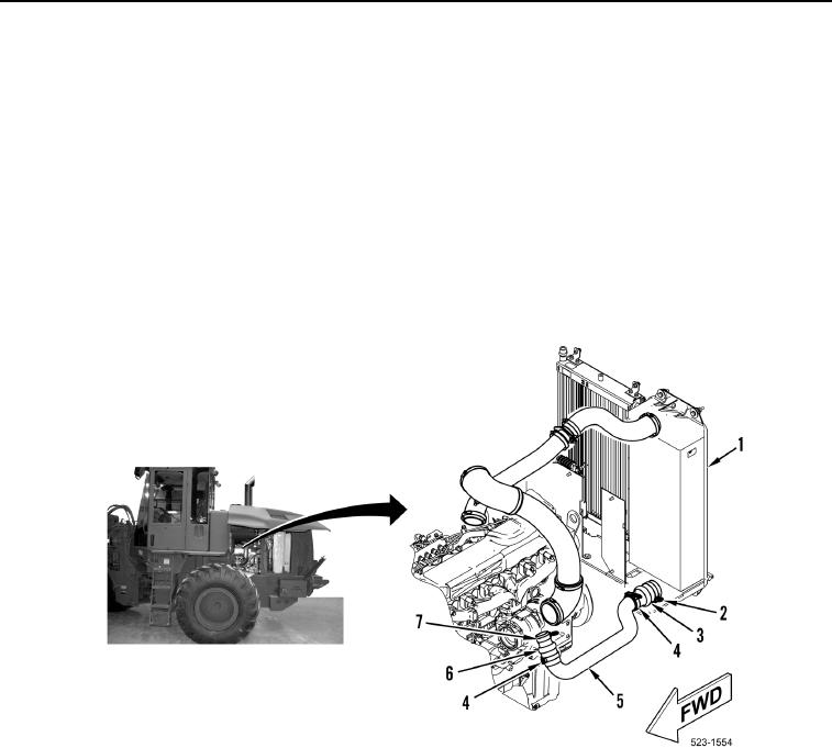
1. Install hose (Figure 13, Item 3) on aftercooler (Figure 13, Item 1) and tighten clamp (Figure 13, Item 2).
2. Install tube (Figure 13, Item 5) on hose (Figure 13, Item 3) and tighten clamp (Figure 13, Item 4).
3. Install hose (Figure 13, Item 6) on tube (Figure 13, Item 5) and turbocharger and tighten two clamps
(Figure 13, Items 7 and 4).
Figure 13. Clamps, Hoses, and Tube.
0207
END OF TASK