
TM 5-3805-298-23-2
0208
INSTALLATION CONTINUED
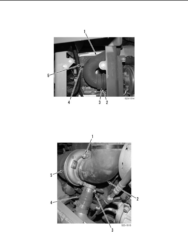
8. Install adapter (Figure 14, Item 3) and exhaust elbow (Figure 14, Item 1) on turbocharger (Figure 14, Item 2).
9. Install two washers (Figure 14, Item 4) and bolts (Figure 14, Item 5) on exhaust elbow (Figure 14, Item 1).
Figure 14. Exhaust Elbow.
0208
10. Install hose (Figure 15, Item 4) on turbocharger (Figure 15, Item 5) and tighten clamp (Figure 15, Item 3).
11. Install hose (Figure 15, Item 2) on turbocharger (Figure 15, Item 5) and tighten clamp (Figure 15, Item 1).
Figure 15. Hoses.
0208