
TM 5-3805-298-23-2
0212
REMOVAL
000212
NOTE
Tag wires and wiring harness to aid installation.
Note routing of wires and wiring harness to aid installation.
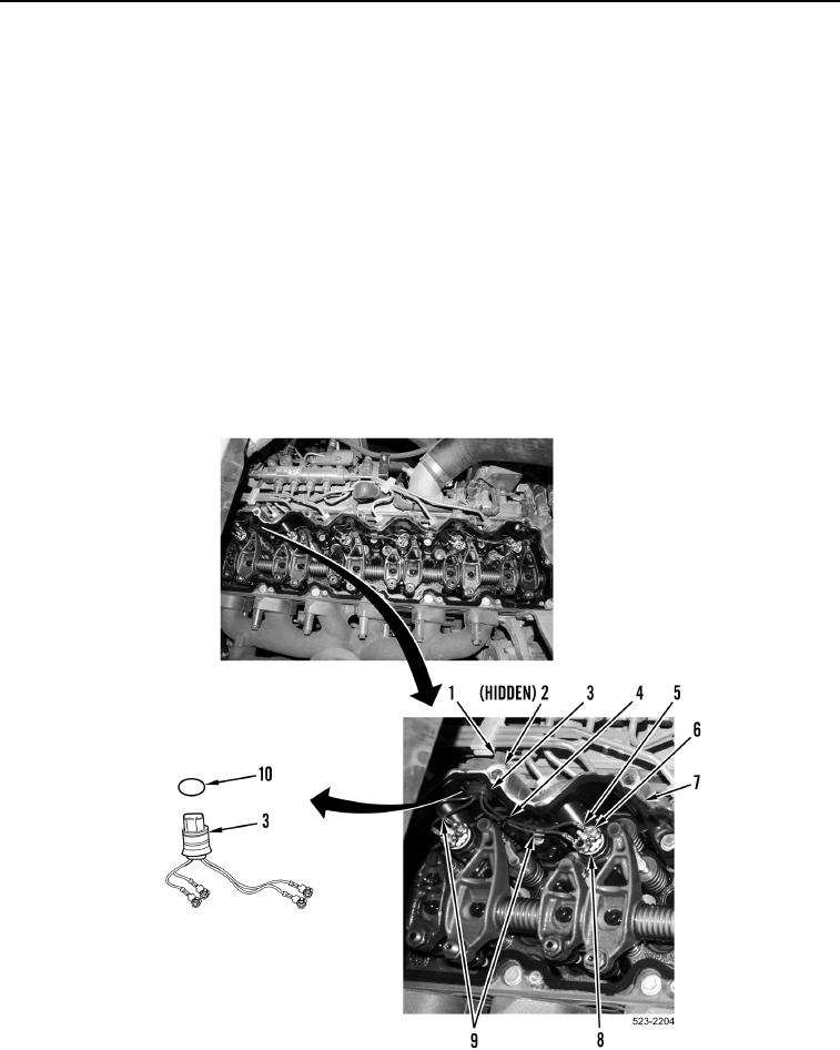
1. Remove four nuts (Figure 1, Item 6) and disconnect four injector jumper harness terminals (Figure 1, Item 5)
from two fuel injectors (Figure 1, Item 8).
NOTE
Note position of tiedown strap to aid installation.
2. Remove tiedown strap (Figure 1, Item 4). Discard tiedown strap.
3. Disconnect engine wiring harness connector (Figure 1, Item 1) from injector jumper harness connector
(Figure 1, Item 3).
4. Remove retaining ring (Figure 1, Item 2) and push injector jumper harness connector (Figure 1, Item 3) and
O-ring (Figure 1, Item 10) inward to remove from valve cover base (Figure 1, Item 7). Discard O-ring.
5. Remove injector jumper harness (Figure 1, Item 9) from machine.
Figure 1. Injector Cylinder 5 and 6 Jumper Harness.
0212
END OF TASK