
TM 5-3805-298-23-4
0372
REMOVAL CONTINUED
NOTE
Tag and mark fittings to aid installation.
Cap or plug fittings and manifold to protect against contamination.
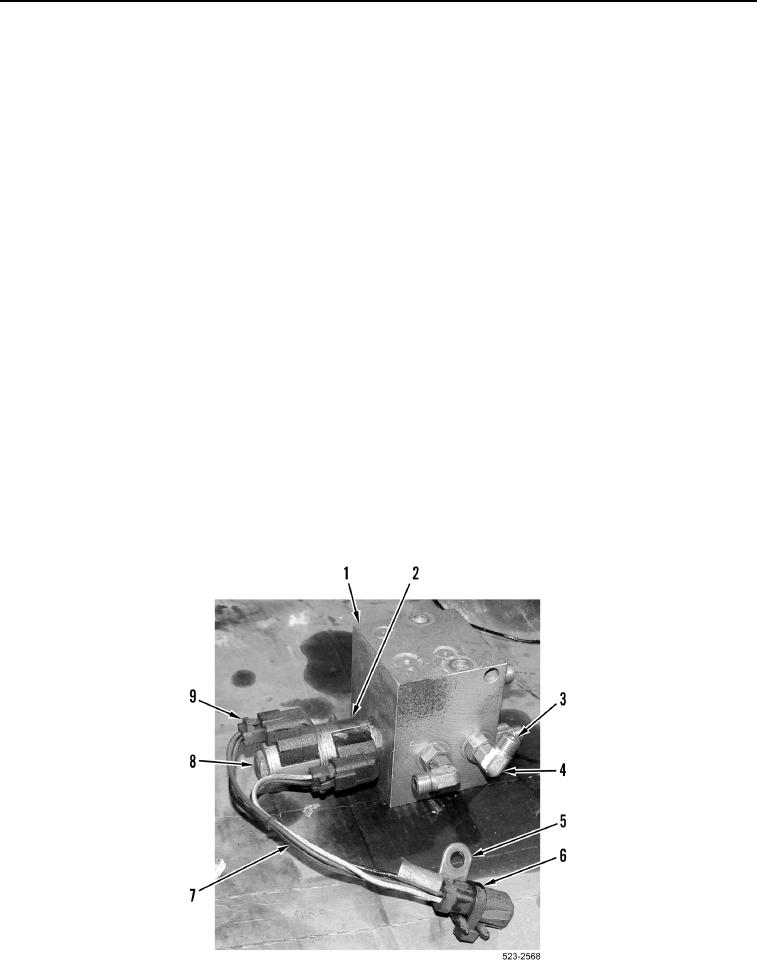
5. Remove six fittings (Figure 4, Item 4) and 12 O-rings (Figure 4, Item 3) from quick coupler control manifold
(Figure 4, Item 1). Discard O-rings.
NOTE
Note location of tiedown strap and ladder clip on solenoid wiring harness to aid
installation.
6. Remove tiedown strap (Figure 4, Item 6) and ladder clip (Figure 4, Item 5) from solenoid wiring harness
(Figure 4, Item 7). Discard tiedown strap.
NOTE
Tag and mark wiring harness connectors to aid installation.
7. Disconnect two solenoid wiring harness connectors (Figure 4, Item 9) and remove solenoid wiring harness
(Figure 4, Item 7) from solenoid coil (Figure 4, Item 2).
NOTE
Note orientation of solenoid coil to aid installation.
8. Remove nut (Figure 4, Item 8) and solenoid coil (Figure 4, Item 2) from quick coupler control manifold
(Figure 4, Item 1).
Figure 4. Quick Coupler Control Manifold Fittings.
0372