
TM 5-3805-298-23-4
0372
INSTALLATION CONTINUED
NOTE
Install solenoid coil as noted during removal.
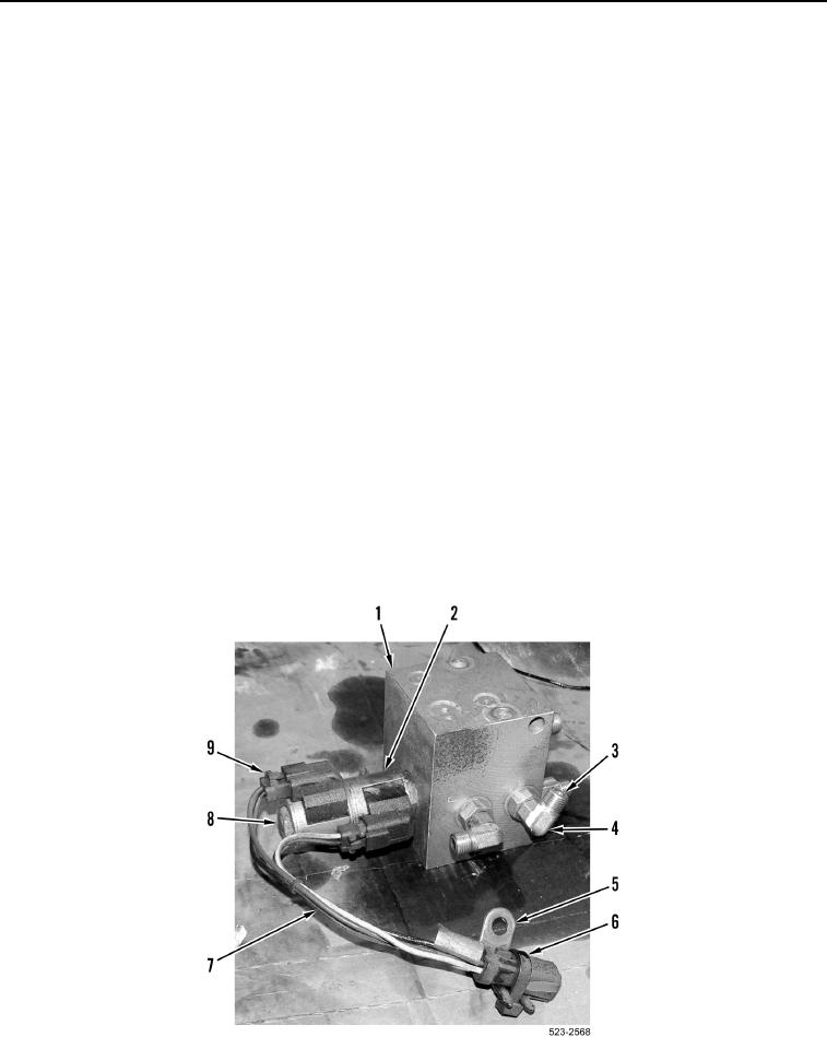
3. Install solenoid coil (Figure 7, Item 2) and nut (Figure 7, Item 8) on quick coupler control manifold
(Figure 7, Item 1).
NOTE
Install wiring harness connectors as noted during removal.
4. Install two solenoid wiring harness connectors (Figure 7, Item 9) and solenoid wiring harness (Figure 7, Item 7)
on solenoid coil (Figure 7, Item 2).
NOTE
Install tiedown strap and ladder clip as noted during removal.
5. Install ladder clip (Figure 7, Item 5) and new tiedown strap (Figure 7, Item 6) on solenoid wiring harness
(Figure 7, Item 7).
NOTE
Remove caps and plugs and install fittings as noted during removal.
6. Install 12 new O-rings (Figure 7, Item 3) and six fittings (Figure 7, Item 4) on quick coupler control manifold
(Figure 7, Item 1).
Figure 7. Quick Coupler Control Manifold Fittings.
0372