
TM 5-3805-298-23-4
0388
REMOVAL CONTINUED
NOTE
Note routing of hoses to aid installation.
Tag and mark hoses and fittings to aid installation.
Cap or plug hose ends and fittings to protect against contamination.
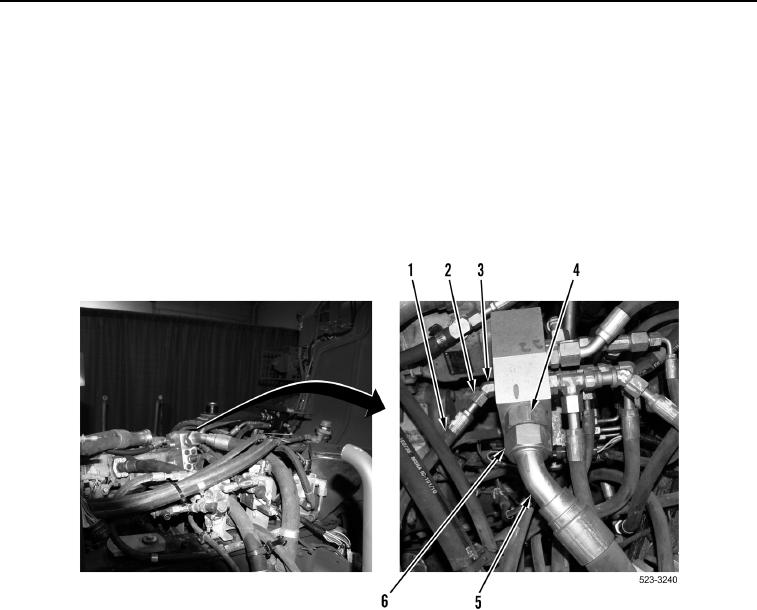
2. Loosen tube nut (Figure 2, Item 6) and remove implement return hose (Figure 2, Item 5) from fitting
(Figure 2, Item 4).
3. Loosen tube nut (Figure 2, Item 2) and remove hose (Figure 2, Item 1) from elbow (Figure 2, Item 3).
Figure 2. Implement Return Hose at Steering Manifold.
0388