
TM 5-3805-298-23-4
0387
REMOVAL CONTINUED
000387
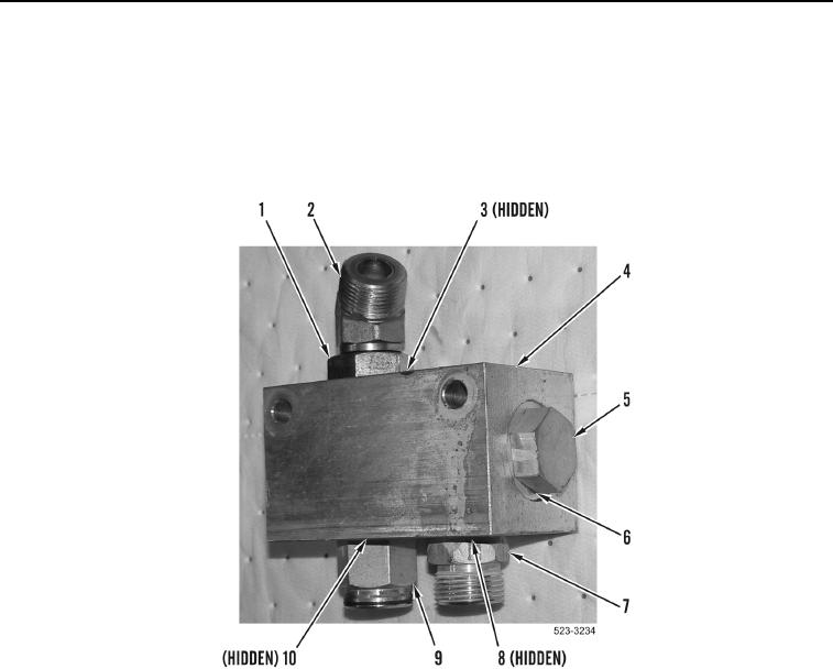
5. Remove check valve (Figure 3, Item 7) and O-ring (Figure 3, Item 8) from manifold (Figure 3, Item 4).
6. Remove fitting (Figure 3, Item 9) and O-ring (Figure 3, Item 10) from manifold (Figure 3, Item 4).
7. Loosen jam nut (Figure 3, Item 1) and remove elbow fitting (Figure 3, Item 2) and O-ring (Figure 3, Item 3) from
manifold (Figure 3, Item 4).
8. Remove two plugs (Figure 3, Item 5) and O-rings (Figure 3, Item 6) from manifold (Figure 3, Item 4).
Figure 3. Manifold.
0387
END OF TASK
CLEANING AND INSPECTION
000387
Clean and inspect all parts IAW Mechanical General Maintenance Instructions (WP 0172).
END OF TASK