
TM 5-3805-298-23-4
0388
REMOVAL CONTINUED
NOTE
Note orientation of fittings to aid installation.
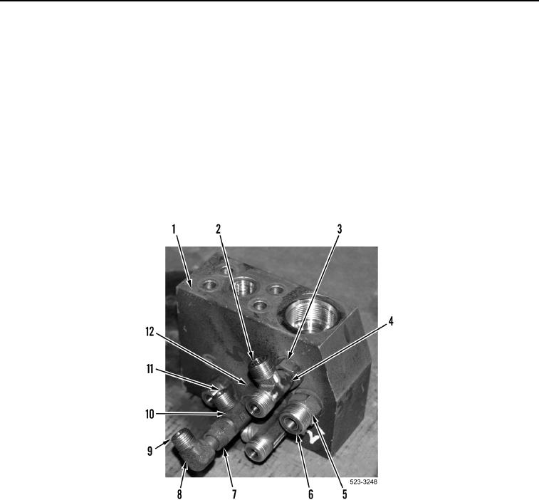
19. Loosen nut (Figure 10, Item 7) and remove elbow (Figure 10, Item 8) and O-ring (Figure 10, Item 9) from tee
fitting (Figure 10, Item 10). Discard O-ring.
20. Loosen two jam nuts (Figure 10, Item 3) and remove two tee fittings (Figure 10, Item 4) and six O-rings
(Figure 10, Item 2) from steering manifold (Figure 10, Item 1). Discard O-rings.
21. Remove two fittings (Figure 10, Item 5) and four O-rings (Figure 10, Item 6) from steering manifold (Figure 10,
Item 1). Discard O-rings.
22. Loosen tube nut (Figure 10, Item 12) and remove tee fitting (Figure 10, Item 10) and three O-rings (Figure 10,
Item 11) from steering manifold (Figure 10, Item 1).
Figure 10. Steering Manifold Fittings.
0388