
TM 5-3805-298-23-4
0398
RIGHT BATTERIES REMOVAL CONTINUED
NOTE
Tag and mark electrical connectors and note cable routing to aid installation.
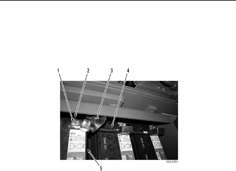
2. Position three negative cable boots (Figure 2, Item 3) aside.
3. Loosen three nuts (Figure 2, Item 2), cable clamps (Figure 2, Item 1), and remove negative cable
(Figure 2, Item 4) from three batteries (Figure 2, Item 5). Position cable aside.
Figure 2. Right Battery Negative Connections.
0398