
TM 5-3805-298-23-4
0406
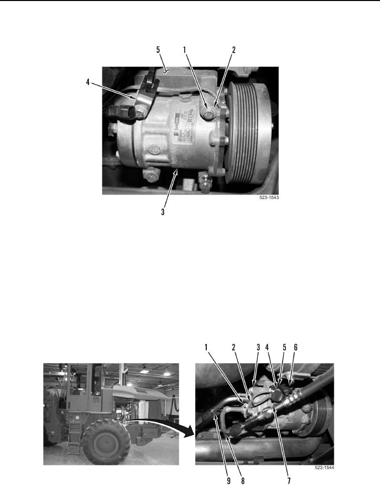
A/C COMPRESSOR INSTALLATION CONTINUED
6. Install A/C compressor (Figure 10, Item 3), ladder clip (Figure 10, Item 4), four washers (Figure 10, Item 2),
and bolts (Figure 10, Item 1) on A/C compressor bracket (Figure 10, Item 5).
Figure 10. Bolts, Washers, Ladder Clip, and A/C Compressor.
0406
NOTE
Route wiring harness and install wiring harness connectors and tiedown strap as noted
during removal.
7. Connect engine wiring harness (Figure 11, Item 6) on wiring harness connector (Figure 11, Item 4).
8. Install tiedown strap (Figure 11, Item 5) on engine control wiring harness connector (Figure 11, Item 6) and clip
(Figure 11, Item 7).
9. Position A/C lines (Figure 11, Items 8 and 9) to A/C compressor (Figure 11, Item 3) and install plate
(Figure 11, Item 2) and bolt (Figure 11, Item 1) on A/C compressor (Figure 11, Item 3).
Figure 11. A/C Lines, Tiedown Strap, and Connector.
0406