
TM 5-3805-298-23-4
0406
A/C COMPRESSOR INSTALLATION CONTINUED
NOTE
Do not over tighten A/C high pressure switch.
Install wiring harness connector as noted during removal.
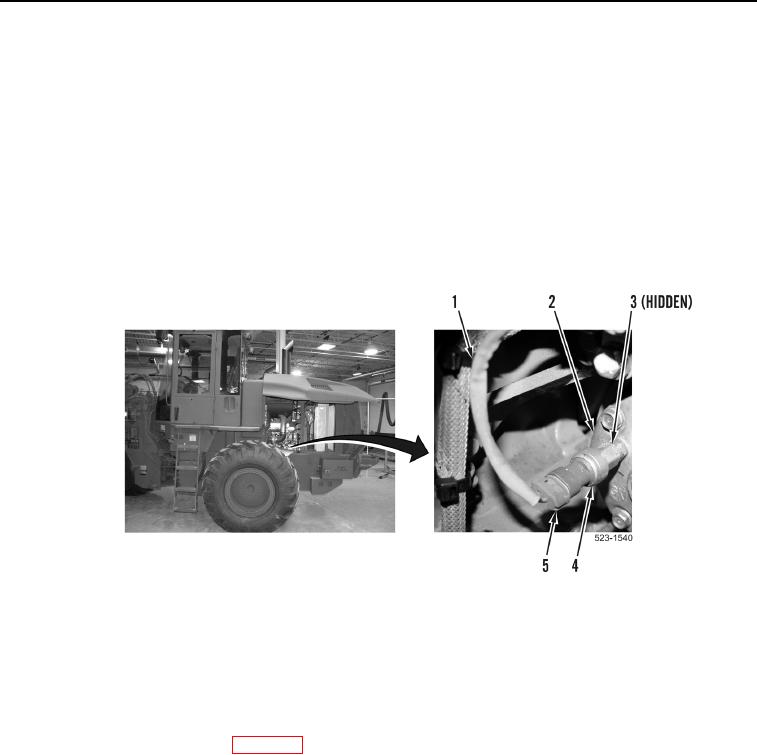
10. Install new O-ring (Figure 12, Item 3) on A/C compressor (Figure 12, Item 2).
11. Install A/C high pressure switch (Figure 12, Item 4) on A/C compressor (Figure 12, Item 2).
12. Position engine control wiring harness (Figure 12, Item 1) to A/C compressor (Figure 12, Item 2).
13. Connect engine control wiring harness connector (Figure 12, Item 5) on A/C high pressure switch
(Figure 12, Item 4).
Figure 12. A/C High Pressure Switch.
0406
END OF TASK
FOLLOW-ON TASKS
000406
Install drive belt bracket and tensioner (WP 0239).
Install drive belt (WP 0239).
Evacuate and charge A/C system ((WP 0405).
Verify correct operation of machine (TM 5-3805-298-10).
END OF TASK
END OF WORK PACKAGE
0406-11/(12 blank)