
TM 5-3805-298-23-4
0410
INSTALLATION
000410
NOTE
Route wiring harness as noted during removal.
Install wiring harness connectors and route wiring harness as noted during removal.
Install tiedown straps as noted during removal.
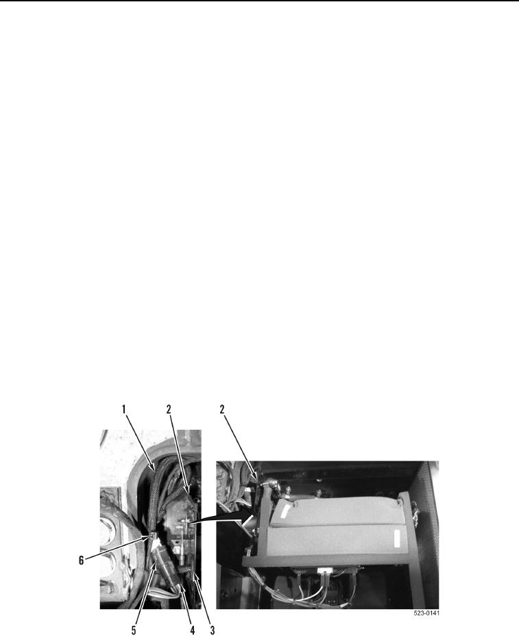
1. Position cab heater wiring harness (Figure 8, Item 1) on machine.
2. Connect three cab heater wiring harness terminals (Figure 8, Item 3) on blower motor resistor
(Figure 8, Item 4).
3. Connect two cab heater wiring harness terminals (Figure 8, Item 5) on A/C temperature switch (Figure 8,
Item 6).
4. Connect cab heater wiring harness connector (Figure 8, Item 8) on blower motor connector (Figure 8, Item 7).
5. Install new tiedown straps (Figure 8, Item 2) on cab heater wiring harness (Figure 8, Item 1).
NOTE
Install wiring harness connectors and route wiring harness as noted during removal.
Install tiedown straps as noted during removal.
6. Position cab heater wiring harness (Figure 9, Item 1) out from cab heater case (Figure 9, Item 2).
7. Install grommet (Figure 9, Item 3) on cab heater wiring harness (Figure 9, Item 1) and cab heater case
(Figure 9, Item 2).
8. Connect cab heater wiring harness connector (Figure 9, Item 5) on lower cab wiring harness connector
(Figure 9, Item 4).
9. Install new tiedown straps (Figure 9, Item 6) on cab heater wiring harness (Figure 9, Item 1).
Figure 9. Lower Cab Wiring Harness Connection.
0410