
TM 5-3805-298-23-4
0420
REMOVAL CONTINUED
NOTE
Tag and note location of wiring harness connectors to aid installation.
Note quantity and location of tiedown straps to aid installation.
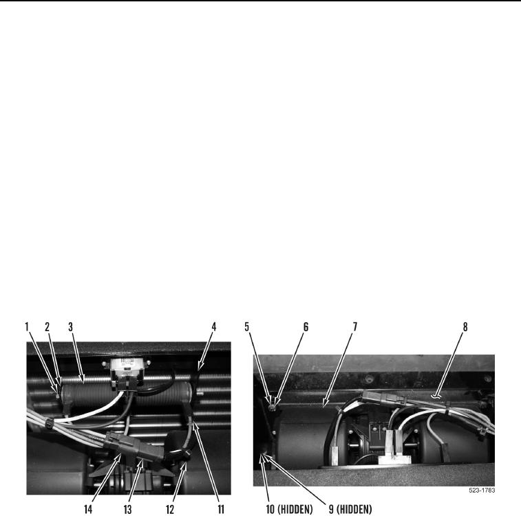
13. Remove tiedown straps (Figure 7, Item 12) as required. Discard tiedown straps.
14. Disconnect three cab heater wiring harness terminals (Figure 7, Item 11) from resistor (Figure 7, Item 3).
NOTE
Note position and location of washers,
15. Remove bolt (Figure 7, Item 1), three washers (Figure 7, Item 2), and resistor (Figure 7, Item 3) from bracket
(Figure 7, Item 4).
16. Disconnect blower wiring harness connector (Figure 7, Item 13) from cab heater wiring harness connector
(Figure 7, Item 14).
17. Remove two bolts (Figure 7, Item 5) and washers (Figure 7, Item 6) from blower motor (Figure 7, Item 7).
18. Remove two locknuts (Figure 7, Item 9) and washers (Figure 7, Item 10) from blower motor (Figure 7, Item 7).
Discard locknuts.
19. Remove blower motor (Figure 7, Item 7) from case (Figure 7, Item 8).
Figure 7. Blower Motor and Resistor.
0420