
TM 5-3805-298-23-4
0420
INSTALLATION CONTINUED
000420
NOTE
Connector wiring harness connectors as noted during removal.
Install tiedown straps as noted during removal.
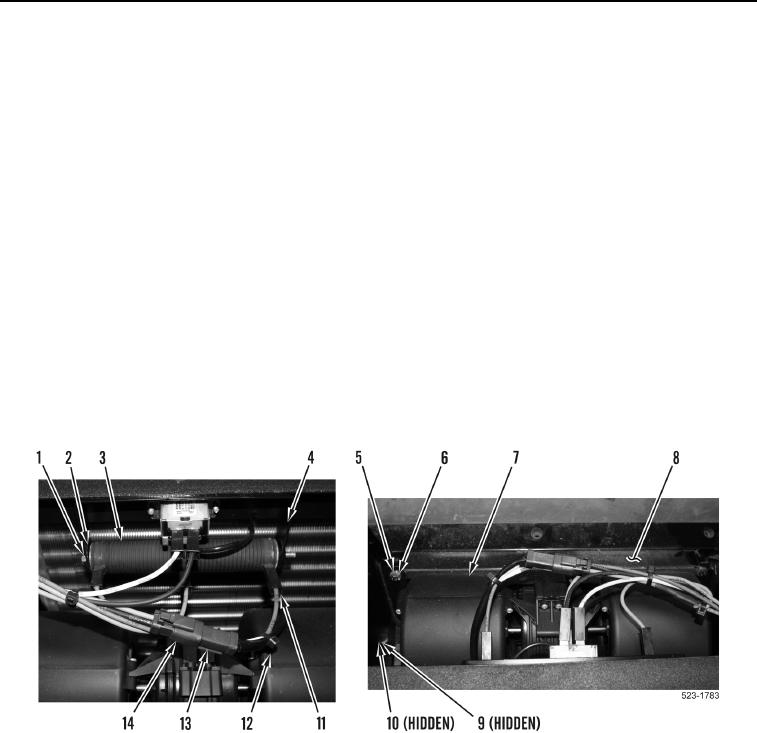
2. Install blower motor (Figure 9, Item 7) in case (Figure 9, Item 8).
3. Install two washers (Figure 9, Item 10) and new locknuts (Figure 9, Item 9) on blower motor (Figure 9, Item 7).
4. Install two washers (Figure 9, Item 6) and bolts (Figure 9, Item 5) on blower motor (Figure 9, Item 7).
5. Connect cab heater wiring harness connector (Figure 9, Item 14) to blower wiring harness connector
(Figure 9, Item 13).
NOTE
Install washers as noted during removal.
6. Install resistor (Figure 9, Item 3), three washers (Figure 9, Item 2), and bolt (Figure 9, Item 1) on bracket
(Figure 9, Item 4).
7. Connect three cab heater wiring harness terminals (Figure 9, Item 11) to resistor (Figure 9, Item 3).
8. Install new tiedown straps (Figure 9, Item 12) as required.
Figure 9. Blower Motor and Resistor.
0420