
6
TM 5-3805-298-23-4
FIELD MAINTENANCE
-
SCHEMATICS INTRODUCTION
04
26
ELECTRICAL SCHEMATICS
000426
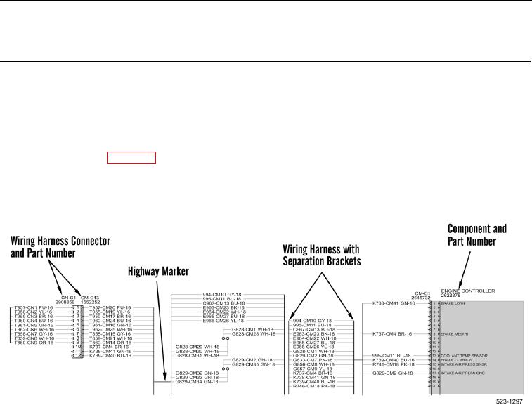
The electrical schematics used on the 924H Loader use symbols and connecting lines to depict how a system
works. The symbols are identified on a separate page. The connecting lines represent a combination of wires,
connectors, and components. A series of highways reduces the number of wires crossing over one another and
ensures maximum available space on each page.
The Schematics Index (WP 0427) lists each schematic foldout included in the book.
Components and wiring harness connectors are identified by the manufacturer's nomenclature and by part
number. Each wire and wiring harness connector also has a unique number designation within each wiring
harness.
Figure 1. Example of a Wiring Harness Schematic.
0426