TM 55-607/NAVSEA OP 3221 Rev 2
unit load, provided the cargo (dimensions do not appreciably exceed those of the normal 40 by 48 inch palletized load,
and the load is not unusually heavy. In all cases, the primary consideration is to eliminate any possibility of the cargo
shifting into the void.
f. Figure 8-10 illustrates the addition of 2 by 3 inch minimum vertical and horizontal lacing to stabilize the securing
structure. Lacing is installed in the manner indicated previously in figure 8-4 and (secured to an overhead structure to
prevent vertical displacement. In the compartment shown, it is desirable to block-stow by levels; that is, a full floor is laid
over the cargo after it has been stowed two high in order that the following tier can be extended once again to the hull.
This technique also finds application in bypassing the turn of the bilge or other low-level obstructions. As shown in figure
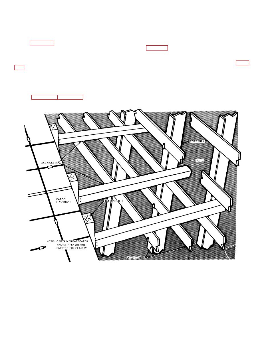
8-11, 4 by 4-inch vertical supports, often referred to as "stiff legs," are installed near the sweatboards. Horizontal 4- by 4-
inch crossmembers are secured to the uprights contacting the cargo and are secured to the uprights at the opposite end
to the stiff legs. If the void at the wings is relatively large, optional flooring runners are laid fore and aft over adjacent
horizontal supports, and a lower course of 2 by 6-inch stripping is emplaced, spaced about 3 inches apart. Finally, 2 by
10-inch upper course flooring is installed, creating a solid support for the next tier of cargo. If the upper course is nailed
to the lower course, 2 by 6-inch lumber is adequate. Cargo is again extended to the hull in resuming the stowage
pattern. Figures 8-12 through 8-17 illustrate in detail the process of block-stowing cargo by levels.
Figure 8-12. Bracing uprights to the hull (hull blocking technique).
8-13


