
14
TM 5-2420-231-23-1
FIELD MAINTENANCE
-
HOW TO USE ON-BOARD DIAGNOSTICS
000
6
Introduction, Using the Front Display Panel, Transmission Controller Diagnostic Faults,
Pilot Controller Diagnostic Faults
INTRODUCTION
0006
The Backhoe Loader (BHL) has two electronic control modules: pilot controller and transmission controller. Both
modules are capable of displaying diagnostic faults. The transmission controller uses the front panel to display the
transmission diagnostic faults. The pilot controller uses a single LED on the controller body and will flash up to four
times between pauses indicating different malfunctions.
USING THE FRONT DISPLAY PANEL
0006
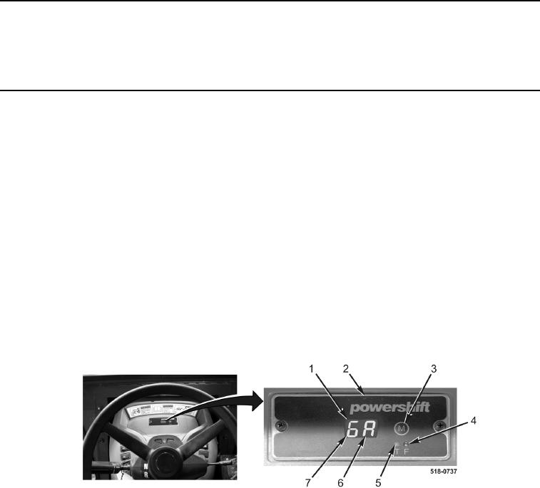
The transmission controller displays operational mode and test information for the operator and maintainer using
the LED display screen (Figure 1, Item 1) on the front display panel (Figure 1, Item 2). The front display panel
(Figure 1, Item 2) consists of the following:
LED display screen (Figure 1, Item 1) made up of two red seven-segment LEDs (Figure 1, Items 6 and 7).
Mode Button (Figure 1, Item 3).
T-Lamp (Figure 1, Item 5), yellow in color.
F Lamp (Figure 1, Item 4), red in color.
At startup, the F lamp (Figure 1, Item 4) will illuminate and "GA" will be displayed momentarily on LED screen
(Figure 1, Item 1) as the transmission controller performs a self-check.
Figure 1. Front Display Panel.
0006