
TM 5-2420-231-23-1
0023
Table 1. Fuel Level Gauge Does Not Function or Is Inaccurate - Continued.
023
MALFUNCTION
TEST OR INSPECTION
CORRECTIVE ACTION
11. Remove front instrument panel
Fuel Level Gauge Does Not
right-side cover (WP 0176).
Function or Is Inaccurate -
Continued
12. Disconnect side console wiring
harness connector (WP 0007, Fig-
ure 24) from main chassis wiring
harness connector (WP 0007, Fig-
ure 25) (WP 0170).
13. Using a digital multimeter, mea-
Resistance 5.0 Ohms or Less -
sure resistance between side con-
Disconnect fuel sending unit eyelet from
sole wiring harness connector (WP
ground.
0007, Figure 28) terminal 20 and
Proceed to step 14.
side console wiring harness con-
Resistance Greater Than 5.0 Ohms -
nector (WP 0007, Figure 24) termi-
Replace side console wiring harness
nal 3B. Resistance should be 5.0
(WP 0170).
ohms or less.
Proceed to step 17.
14. Using a digital multimeter, mea-
Resistance 5.0 Ohms or Less -
sure resistance between rear main
Proceed to step 15.
chassis wiring harness connector
Resistance Greater Than 5.0 Ohms -
(WP 0007, Figure 25) terminal 3B
Replace main chassis wiring harness
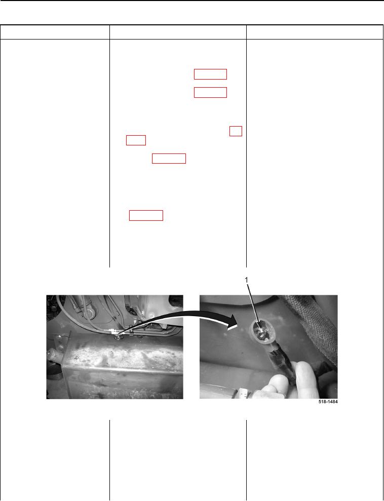
and fuel sending unit eyelet (Fig-
(WP 0154).
ure 9, Item 1). Resistance should
Install instrument cluster (WP 0177),
be 5.0 ohms or less.
and front instrument panel right-side
cover (WP 0176).
Proceed to Test Step 5.
Figure 9. Fuel Sending Unit Eyelet.
0023