
TM 5-2420-231-23-1
0023
Table 1. Fuel Level Gauge Does Not Function or Is Inaccurate - Continued.
023
MALFUNCTION
TEST OR INSPECTION
CORRECTIVE ACTION
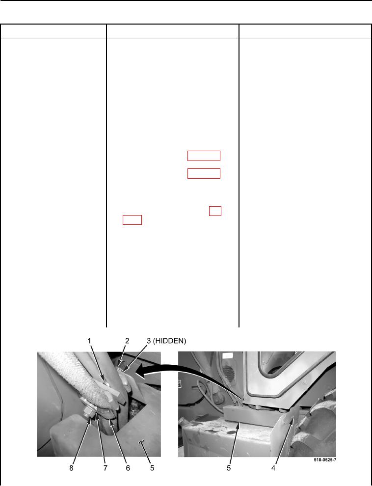
5. Install cover (Figure 6, Item 5), two
Fuel Level Gauge Does Not
spacers (Figure 6, Item 1), three
Function or Is Inaccurate -
clamps (Figure 6, Item 6), washer
Continued
(Figure 6, Item 3), bolt (Figure 6,
Item 2), new lockwasher (Figure 6,
Item 7), and nut (Figure 6, Item 8)
on machine.
6. Install bolt on cover (Figure 6,
Item 4). Proceed to Test Step 5.
7. Remove front instrument panel
right-side cover (WP 0176).
8. Disconnect side console wiring
harness connector (WP 0007, Fig-
ure 24) from main chassis wiring
harness connector (WP 0007, Fig-
ure 25) (WP 0170).
9. Using a digital multimeter, test for
Continuity - Replace main chassis
continuity between main chassis
wiring harness (WP 0154).
wiring harness connector (WP
Proceed to Test Step 5.
0007, Figure 24) terminal 3B and
No Continuity - Replace side console
machine ground. There should be
wiring harness (WP 0170).
no continuity.
Proceed to step 10.
10. Install cover (Figure 6, Item 5), two
spacers (Figure 6, Item 1), three
clamps (Figure 6, Item 6), washer
(Figure 6, Item 3), bolt (Figure 6,
Item 2), new lockwasher (Figure 6,
Item 7), and nut (Figure 6, Item 8)
on machine.
11. Install bolt on cover (Figure 6,
Item 4). Proceed to Test Step 5.
Figure 6. Fuel Tank Cover.
0023