
TM 5-2420-231-23-1
0034
Table 1. Parking Brake Indicator Fault - Continued.
034
MALFUNCTION
TEST OR INSPECTION
CORRECTIVE ACTION
Parking Brake Indicator
Test Step 7. Check for Faulty
Fault - Continued
Instrument Cluster.
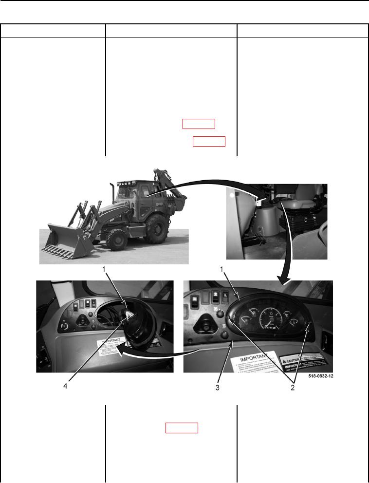
1. Remove two screws (Figure 5,
Item 2) from instrument panel clus-
ter (Figure 5, Item 1), pull instru-
ment panel cluster (Figure 5,
Item 1) from bezel (Figure 5,
Item 3), and disconnect side con-
sole wiring harness connector
(Figure 5, Item 4) (WP 0007, Fig-
ure 28) from instrument panel clus-
ter (Figure 5, Item 1) (WP 0007,
Figure 29) (WP 0177).
Figure 5. Instrument Cluster.
0034
2. Using a digital multimeter, mea-
Resistance 12 to 16 Ohms - Proceed
sure resistance between instru-
to Test Step 8.
ment cluster (WP 0007, Figure 29)
Resistance Greater Than 16 Ohms -
terminals 7 and 1. Resistance
Replace parking brake indicator bulb on
should be 12 to 16 ohms.
instrument cluster (WP 0177).
Proceed to Test Step 11.