
TM 5-2420-231-23-1
0039
Table 1. Alarm Signal Does Not Function - Continued.
039
MALFUNCTION
TEST OR INSPECTION
CORRECTIVE ACTION
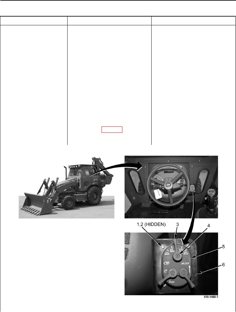
3. Remove screw (Figure 2, Item 4),
Alarm Signal Does Not
and lever (Figure 2, Item 3) from
Function - Continued
light control switch (Figure 2,
Item 5).
4. Remove four screws (Figure 2,
Item 1), washers (Figure 2,
Item 2), and light control switch
(Figure 2, Item 5) from bracket
(Figure 2, Item 6).
5. Install lever (Figure 2, Item 3) and
screw (Figure 2, Item 4) on light
control switch (Figure 2, Item 5).
6. Turn light control switch to the
SER. DRIVE position (TM 5-2420-
231-10).
7. Using a digital multimeter, mea-
Resistance 5.0 Ohms or Less -
sure resistance between light con-
Proceed to Test Step 4.
trol switch (WP 0007, Figure 72)
Resistance Greater Than 5.0 Ohms -
terminals F and J. Resistance
Replace light control switch (WP 0175).
should be 5.0 ohms or less.
Proceed to Test Step 9.
Figure 2. Light Control Switch and Driving Lights Switch.
0039