
TM 5-2420-231-23-1
0086
CHECKING OUTPUT OF REAR SECTION CONTINUED
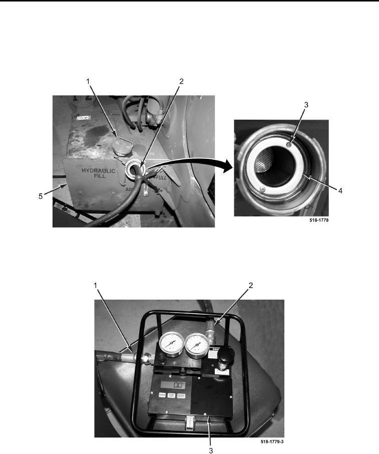
6. Remove cap (Figure 51, Item 1), two screws (Figure 51, Item 3), and screen (Figure 51, Item 4) from reservoir
(Figure 51, Item 5)
7. Insert outlet hose (Figure 51, Item 2) until it touches bottom of hydraulic reservoir (Figure 51, Item 5) and
secure hose in place.
Figure 51. Hydraulic Reservoir.
0086
8. Connect inlet hose (Figure 52, Item 1) and outlet hose (Figure 52, Item 2) to flowmeter (Figure 52, Item 3).
Figure 52. Flowmeter Connections.
0086