
TM 5-2420-231-23-1
0086
LOADER RELIEF VALVE CONTINUED
Adjustment
0086
NOTE
Loader relief valve is in inlet section of loader control valve.
Only first stage of loader relief valve is adjustable. If second stage only is low, replace
pressure relief valve.
1. Remove front floor cover plate (WP 0306) and right floor cover plate (WP 0277).
NOTE
Make 1/4 or less turns of adjusting nut.
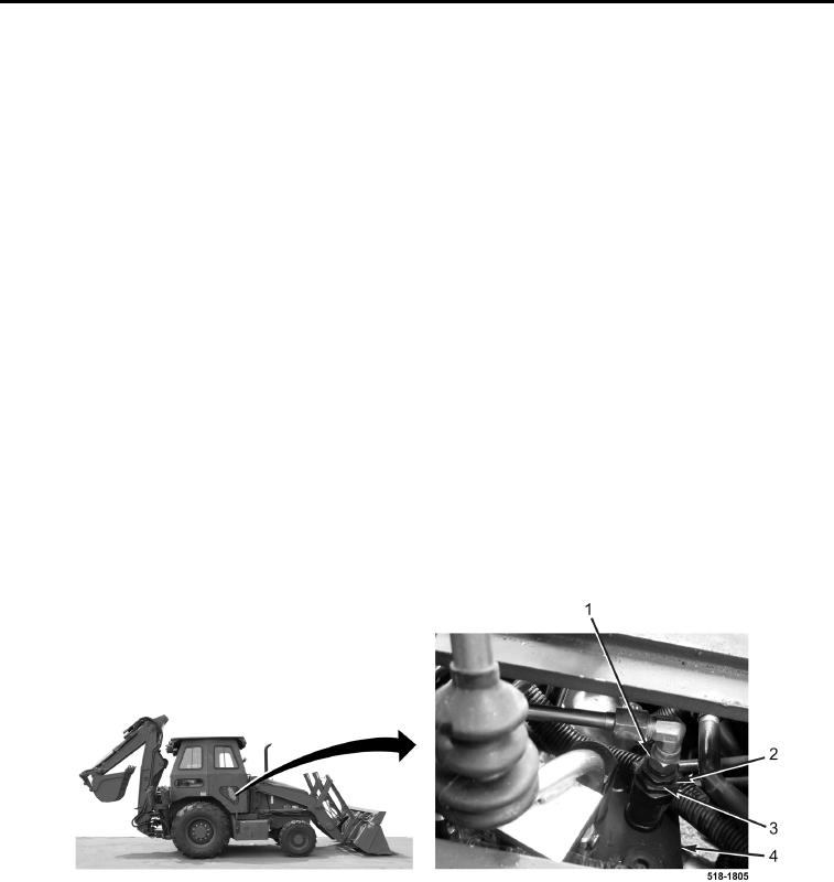
2. Loosen tube nut (Figure 48, Item 1) and locknut (Figure 48, Item 3) on loader relief valve (Figure 48, Item 4).
Turn adjusting nut (Figure 48, Item 2) clockwise to increase pressure, and counterclockwise to decrease
pressure. Pressure should be 2,900 to 3,200 psi (20,000 to 22,063 kPa).
3. Tighten tube nut (Figure 48, Item 1).
4. Run engine at 2000 rpm. Hold manual control lever in raise (dead head) position until loader stops moving.
5. Hold manual control lever in raise (dead head) position and read pressure gauge (Figure 47, Item 2).
6. When the pressure is correct, tighten locknut (Figure 48, Item 3).
7. Lower loader to ground (TM 5-2420-231-10).
8. Decrease engine speed to idle and turn machine off (TM 5-2420-231-10).
9. Install front floor cover plate (WP 0306) and right floor cover plate (WP 0277).
Figure 48. Loader Relief Valve.
0086
END OF TASK