
TM 5-2420-231-23-1
0086
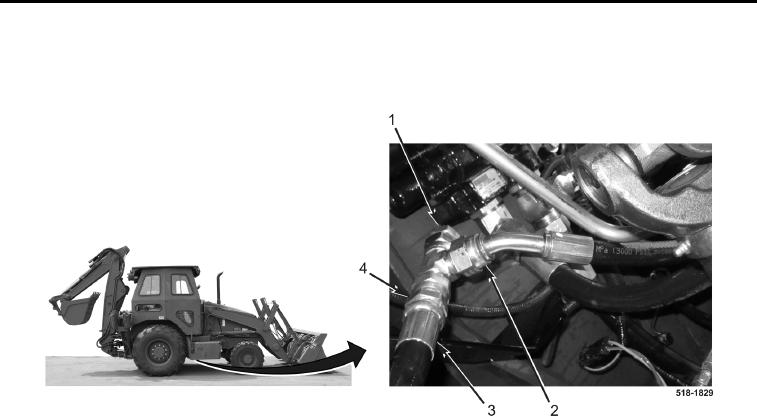
CHECKING OUTPUT OF FRONT SECTION CONTINUED
2. Connect flowmeter inlet hose (Figure 55, Item 3) and pump output hose (Figure 55, Item 2) to tee 1-1/16-12M
JIC x 1-1/16-12F JIC SIW x 1-1/16-12M JIC (Figure 55, Item 4) and install plug (Figure 55, Item 1) to tee.
Figure 55. Pump Outlet Hose.
0086
CAUTION
Load valve must be rotated completely counterclockwise (open) before starting engine to
prevent blowing flowmeter relief valve.
3. Start and run the engine until oil is at operating temperature (TM 5-2420-231-10). If oil is not at operating
temperature, perform the following:
a. Slowly close load valve (Figure 56, Item 2) on flowmeter (Figure 56, Item 3) until pressure gauge
(Figure 56, Item 1) indicates 1,000 psi (6,895 kPa).
b. Run engine at full throttle until temperature is 125F (52C).
4. Run engine at 2,000 rpm.
5. Press POWER button (Figure 56, Item 5) to activate flow gauge (Figure 56, Item 4).
6. Uncurl bucket (TM 5-2420-231-10) and hold in deadhead position.
7. Record flow reading from flow gauge (Figure 56, Item 4).
8. Slowly close load valve (Figure 56, Item 2) until pressure gauge (Figure 56, Item 1) reads 2,000 psi
(13,789 kPa). Record flow reading from flow gauge (Figure 56, Item 4).