
TM 5-2420-231-23-1
0086
RIGHT SOLENOID VALVE FOR RIDE CONTROL (ACCUMULATOR)
0086
1. Make sure that oil side of accumulator is completely discharged:
a. Turn ignition switch to on position and operate engine at low idle (TM 5-2420-231-10).
b. Put ride control switch in on position (TM 5-2420-231-10).
c.
With loader lowered to floor, put manual control lever in float position (TM 5-2420-231-10).
d. Stop engine. Turn ignition switch to on position (TM 5-2420-231-10).
e. Move manual control lever in all directions to release any pressure in hydraulic circuits. Put manual control
lever in float position (TM 5-2420-231-10).
2. Put ride control switch and ignition switch in off position (TM 5-2420-231-10).
3. Put manual control lever in NEUTRAL position (TM 5-2420-231-10).
WARNING
Allow hydraulic system to cool before performing procedure. Hot hydraulic fluid can cause
severe burns. Wear eye, hand, and skin protection when working with heated parts.
Hydraulic oil is very slippery. Immediately wipe up any spills.
Failure to follow these warnings may result in injury or death to personnel.
NOTE
Place drain pan to catch hydraulic fluid.
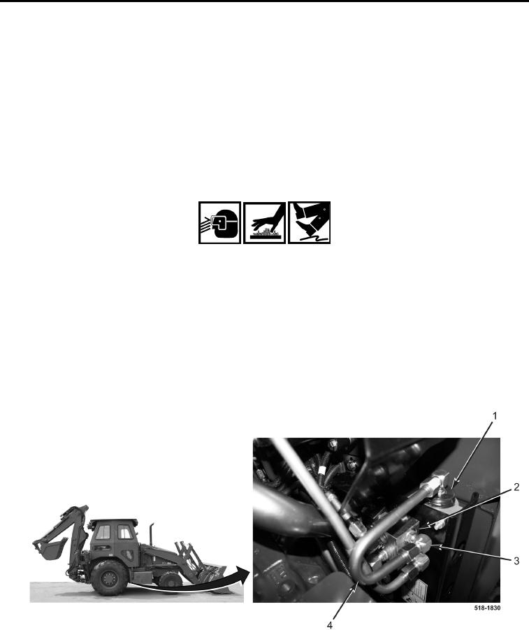
4. Disconnect tube (Figure 66, Item 4) between right solenoid valve (Figure 66, Item 2) and accumulator
(Figure 66, Item 1) from adjustable elbow fitting (Figure 66, Item 3).
Figure 66. Accumulator.
0086